There are two types of fibre-optic branching devices in a PON (Passive Optical Network). One type has a wavelength multiplexer and demultiplexer, the other does not. This article applies to optical branching devices without wavelength multiplexer and demultiplexer (non-wavelength selective) to be used for passive optical networks (PONs). You can click WDM Systems to learn more about optical branching devices with wavelength multiplexer and demultiplexer (wavelength selective).
 
Non-wavelength selective optical branching devices are passive components without a wavelength multiplexer and demultiplexer. They are also called “optical splitters” or “optical couplers”.


Types and configurations

Optical branching components can be classified as one or more of the following:
a) star branching devices: A branching device typically balanced; possessing more than four ports;
b) tree branching devices: A branching device with a single optical input distributed among several outputs, or vice versa.


Technological aspects of optical branching devices

There are several methods used to manufacture non-wavelength selective optical branching devices , and they can be grouped into the following classes:

a) fusion technology

Fusion technology (Figure 1) has proved to be simple, versatile and effective, allowing the industrial implementation of several kinds of branching devices for a variety of applications. With the fused biconic taper (FBT) method, bare or etched fibres are brought into contact, stretched, possibly twisted, and fused so that evanescent mode coupling occurs along the interaction length;

Fiber Fused Biconic Taper (FBT) Coupler
Lfiber have world-class technical solution in the heat treatment of fiber.
Planar Lightwave Circuit (PLC) Technology for Optical Branching Devices

b) Planar lightwave circuit (PLC) technology

Planar waveguide branching devices (Figure 2) are made by photolithographic technology, using parallel processing techniques. To produce the refractive index profile, ions are diffused into a substrate such as glass, semiconductor (silicon), LiNbO3 or polymer. Alternatively, doped silica glass is fabricated by chemical vapour deposition (CVD) or by flame hydrolysis deposition (FHD) and consolidation. The optical profile and the geometrical properties of the guiding structure are defined by photolithographic masking techniques followed by etching;

c) polishing technology

In order to position fibre cores close enough to allow the overlap of the evanescent fields (coupling conditions), the fibre cladding is removed to within a few microns of the core. This controlled removal of the cladding is achieved by mechanical abrasion (polishing).

Fiber Fused Biconic Taper (FBT) Coupler

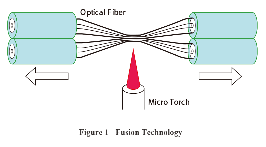
              Figure 3 – Fiber Fused Optical Coupler


Fiber Fused Biconic Taper (FBT) Coupler

A fused biconic taper (FBT) oupler basically consists of two or more parallel optical fibers that have been brought into contact, stretched, possibly twisted, and fused together so that they can split or combine light. (Figure 3)

Important points about fiber fused coupler:

 1. Fused wavelength selective couplers (WDM) are used to either combine or split light of different wavelengths with minimal loss.
 
2. A coupler that splits only a small part (1% to 20%) of the light into one output and leaves most in the other is often called a “tap”. For example light may enter at port 1 and 99% may leave at port 2 and only 1% at port 3. This would be a 99:1 coupler or a 1% tap.
 
3. The “coupling length” is formally defined (at a particular wavelength) as the length at which 100% of the power entering at a particular input port is transferred to the other fibre. 
 
4. The amount of coupling and hence the coupling length is strongly dependent on the separation between the two single-mode cores. The further apart they are the greater the coupling length.
 
Power Transfer in a Resonant Coupler. If two mixed signals (of different wavelengths) are injected into a resonant coupler the power transfer between the waveguides has a different period for each wavelength.

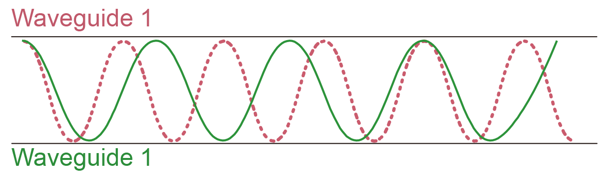
Figure 4 – Power Transfer in a Resonant Coupler. If two mixed signals (of different wavelengths) are injected into a resonant coupler the power transfer between the waveguides has a different period for each wavelength.

 
5. The coupling lengths are strongly wavelength dependent! Different wavelengths yield different coupling lengths. This is shown in Figure 4.

Two mixed signals of different wavelength are shown entering the top left hand port of a coupler. The power transfer between waveguides is shown by the two sinusoids.

This characteristic can be used to construct wavelength selective couplers (fused WDM).
 
Wavelength sensitivity is not always a convenient characteristic. If you want to transport signals in both the 1300 and 1550 bands you want them to be processed through couplers without separation. Fortunately, by careful design of the coupler (mainly careful choice of coupling length) you can achieve a relatively flat response (no separation of wavelengths) for the whole range between 1300 nm and 1550 nm. Couplers designed in this way are called “wavelength flattened couplers”.
 
6. The effect is symmetric. Light entering one of the “exit” ports will leave the device at one of the “entry” ports.
 
7. Light exiting the coupler of the opposite fibre from which it entered is 180° shifted in phase. 
 
8. If the wavelengths are the same (or close together) and the core sizes etc. are also the same then there is no way to couple all of the power from both input ports to the same output port. 
 
9. Optical branching devices can be designed to operate at a single wavelength (e.g., 1310 or 1550 nm), to be wavelength flat (e.g., insensitive to wavelength variations within a single window) or to be wavelength independent (e.g., insensitive to wavelength variations within both the second and third windows, 1260-1360 nm and 1450-1600 nm, or 1260-1360 nm and 1450-1660 nm).


Planar Lightwave Circuit (PLC) Splitter

Planar lightwave circuit (PLC) technology can be used to miniaturize the (fibre-optic) branching component. The right-hand figure shows a prototype 8 branch fibre-optic PLC splitter.
 
The  PLC splitter for PONs are characterized by the term “1 × X” or “2 × X”  where X = 4, 8, 16, 32, or 64. The insertion loss increases as the number of branches is increased.
Lfiber's PLC Splitter
Lfiber’s PLC splitters are GR-1209-CORE and GR-1221-CORE compliant.

Click the following link to learn more and Discover the Fiber-optic World.