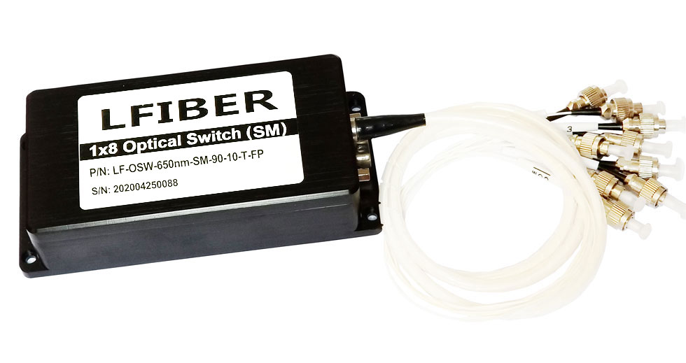
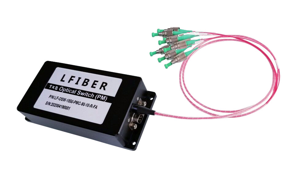
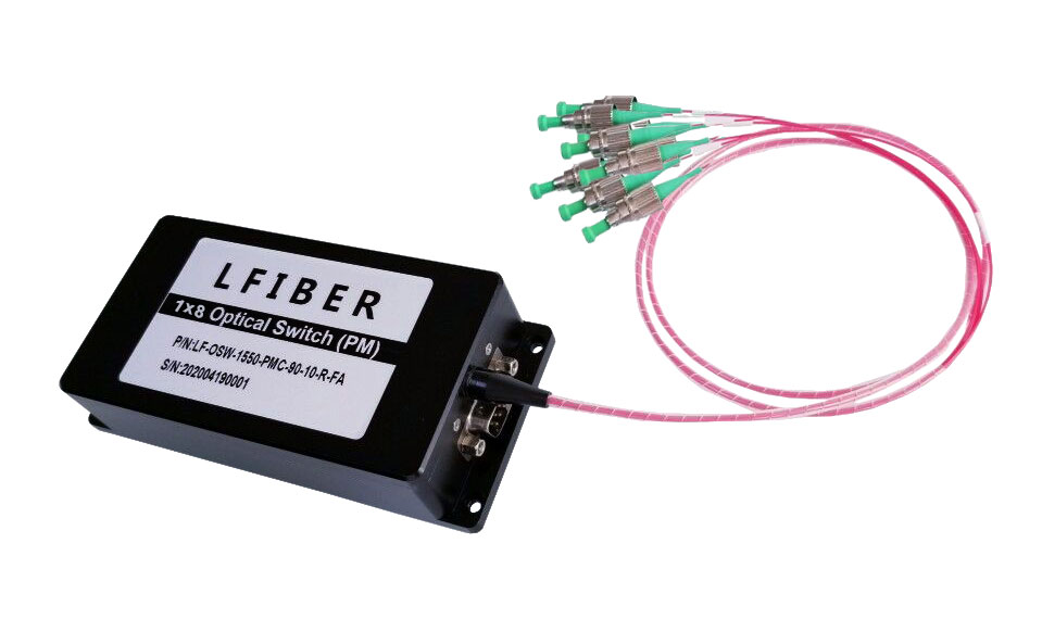
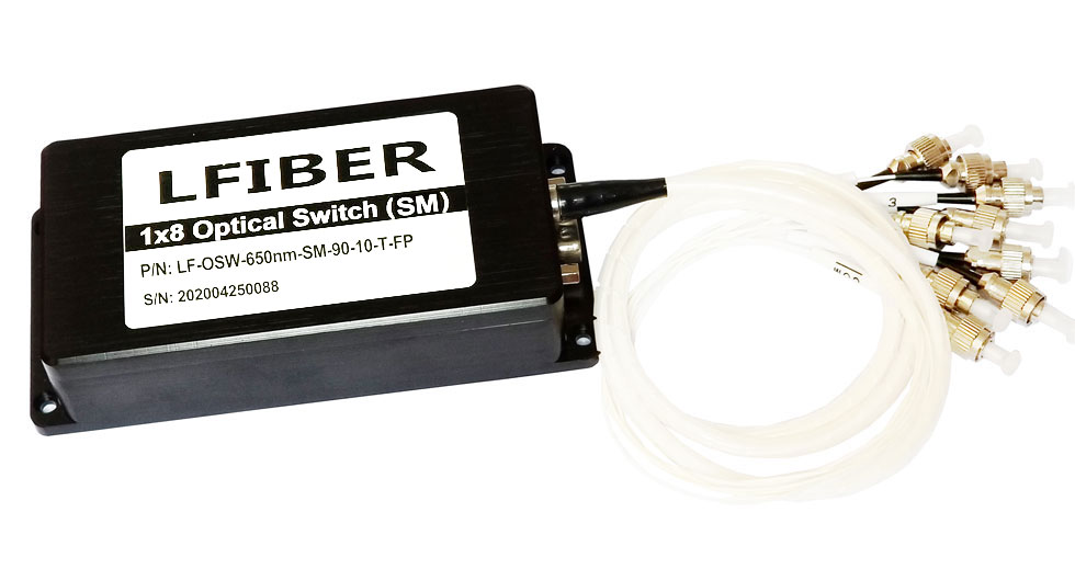
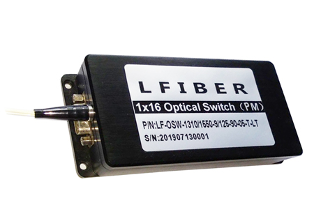
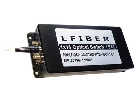
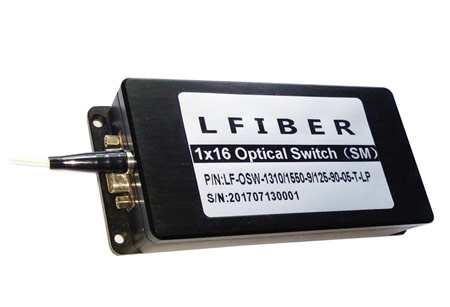
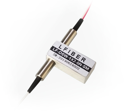
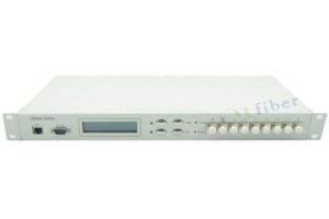
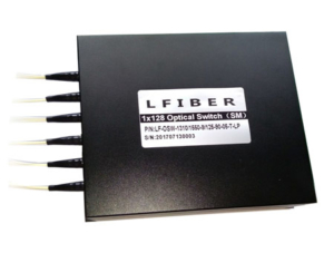
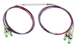
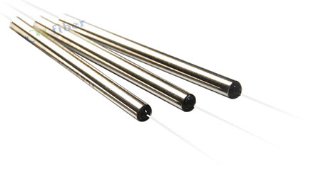
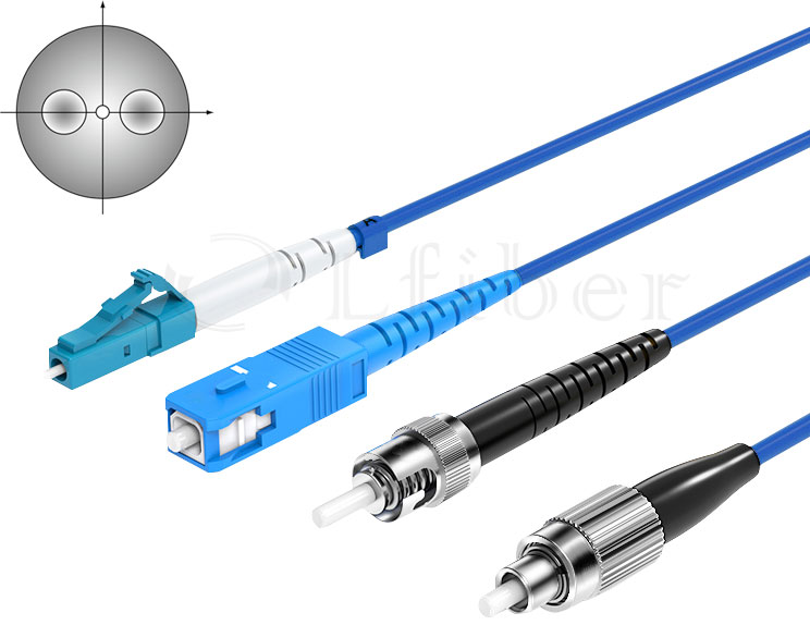
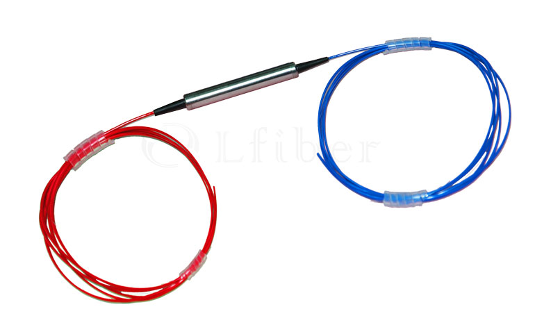
Single Mode Fiber Optic Switches
SM Fibers, VIS-NIR Spectrum, TTL Version
FEATURES OF SM FIBER OPTIC SWITCHES (SINGLE-MODE OPTICAL SWITCH)
- Low Insertion Loss and High Reliability
- Parallel Interface (TTL)
- Modularized Design
- Functions of Breakdown Self-checking and Alarm Warning (TTL)
APPLICATIONS OF SINGLE-MODE FIBER OPTIC SWITCHES (SM OPTICAL SWITCH)
- Optical Signal Switching and Routing
- Optical Network Monitoring
- Testing of Fiber Optic Component
- OTDR Testing
Specifications of the Fiber Optic Switches (Single-Mode Optical Switch)
Number of Channels (N) 1×N (N ≤ 16) or other channel counts on request
Fiber Type Single-mode fibers
Insertion Loss (dB) ≤ 2.0 dB @ 430-670 nm
≤ 1.5 dB @ 780-1250 nm
≤ 1.0 dB @ 1260-1590 nm
≤ 1.5 dB @ 1600-2000 nm
Operating Wavelength Range (nm) 405-2000 nm on request
Testing Wavelength (nm) 405, 450, 480, 532, 650, 780, 850, 980, 1310, 1490, 1550, 1625, 1650, etc.
Return Loss (dB) ≥ 50
Crosstalk (dB) ≥ 70
Wavelength Dependent Loss (dB) ≤ 0.25
Temperature Dependent Loss (dB) ≤ 0.25
Repeatability (dB) ≤ 0.02
Lifetime (cycles) ≥ 10 million
Switching Time (ms) ≤ 8 (adjacent channel)
Power Handling (mW) ≤ 500
Power Supply 5V / 500mA
Control Mode TTL
Connector FC, LC, SC, ST, MPO, etc.
Operating Temperature (℃) -20 to +70
Storage Temperature (℃) -40 to +85
Dimension (mm) 80 × 40 × 32 mm (channel amount ≤ 8)
135 × 64 × 32 mm (channel amount ≤ 16)
- For requests please see the ordering information section and specify the number of channels, operating wavelengths, control mode, connector types, etc.
- Typically, the operating wavelengths of the single-mode fiber optic switches include, but are not limited to, 405nm, 444nm, 445nm, 447nm, 450nm, 454nm, 457nm, 460nm, 462nm, 465nm, 470nm, 473nm, 480nm, 484nm, 488nm, 490nm, 491nm, 501nm, 505nm, 509nm, 510nm, 514nm, 515nm, 520nm, 522nm, 523nm, 526nm, 530nm, 532nm, 540nm, 543nm, 550nm, 552nm, 555nm, 556nm, 561nm, 577nm, 588nm, 589nm, 593.5nm, 594nm, 600nm, 604nm, 607nm, 612nm, 622nm, 627nm, 630nm, 632nm, 633nm, 635nm, 637nm, 638nm, 640nm, 642nm, 647nm, 650nm, 655nm, 656nm, 660nm, 665nm, 666nm, 670nm, 671nm, 680nm, 685nm, 688nm, 689nm, 690nm, 698nm, 705nm, 721nm, 730nm, 750nm, 760nm, 770nm, 780nm, 785nm, 786nm, 790nm, 793nm, 795nm, 800nm, 808nm, 810nm, 825nm, 830nm, 835nm, 845nm, 850nm, 852nm, 860nm, 879nm, 880nm, 885nm, 905nm, 914nm, 915nm, 930nm, 935nm, 938nm, 940nm, 946nm, 960nm, 965nm, 975nm, 976nm, 980nm, 1030nm, 1035nm, 1040nm, 1047nm, 1053nm, 1055nm, 1060nm, 1064nm, 1080nm, 1085nm, 1105nm, 1112nm, 1120nm, 1122nm, 1177nm, 1208nm, 1268nm, 1275nm, 1300nm, 1310nm, 1313nm, 1319nm, 1320nm, 1342nm, 1380nm, 1392nm, 1410nm, 1413nm, 1444nm, 1450nm, 1470nm, 1475nm, 1480nm, 1490nm, 1528nm, 1532nm, 1540nm, 1550nm, 1558nm, 1560nm, 1565nm, 1570nm, 1573nm, 1590nm, 1600nm, 1605nm, 1610nm, 1625nm, 1645nm, 1700nm, 1710nm, 1720nm, 1750nm, 1850nm, 1870nm, 1900nm, 1910nm, 1920nm, 1940nm, 1950nm, 1990nm, and 2000nm. Other operating wavelength requirements are also available on request.
- Standard port/channel counts of the fiber optic switches: 1×2, 1×4, 1×8, 1×16, 1×24, 1×32, 1×48, 1×64, 1×128, etc. Other channel counts are available upon request.
- The fiber optic switches are customizable and the specifications are subject to change without notice.
- For product customization or special requirements, please contact our sales representative.
| Pin Configurations of the Fiber Optic Switches (Single-Mode Optical Switch) |
|---|
ZH 1.5mm 9P or DB-9 Male Connector
| Pin No. | I / O | Signal | Descriptions |
| 1 | Input | D0 | D0-D3 represent channel selection Bit0-Bit3; D0 is low; D3 is high. |
| 2 | Input | D1 | |
| 3 | Input | D2 | |
| 4 | Input | D3 | |
| 5 | Input | RESET | TTL, Low level reset to channel 0. High level means channel selection bits are effective. |
| 6 | Out | READY | TTL, Ready (High = not ready, Low = ready) |
| 7 | Out | ERROR | TTL, Error OR Failure , (High = error, Low = no error) |
| 8 | Power | GND | Ground |
| 9 | Power | VCC | 5.0±5% VDC Power Supply (Max. 500mA) |
| Channel Selection Table of the Fiber Optic Switches (Single-Mode Optical Switch) | |||||
|---|---|---|---|---|---|
| Channel | D0 | D1 | D2 | D3 | RESET |
| COM-0 | x | x | x | x | 0 |
| COM-1 | 0 | 0 | 0 | 0 | 1 |
| COM-2 | 1 | 0 | 0 | 0 | 1 |
| COM-3 | 0 | 1 | 0 | 0 | 1 |
| ... | ... | ... | ... | ... | 1 |
| COM-14 | 1 | 0 | 1 | 1 | 1 |
| COM-15 | 0 | 1 | 1 | 1 | 1 |
| COM-16 | 1 | 1 | 1 | 1 | 1 |
| Dimensions of the Fiber Optic Switches (Single-Mode Optical Switch) |
|---|
Channel Amount (N) ≤ 8
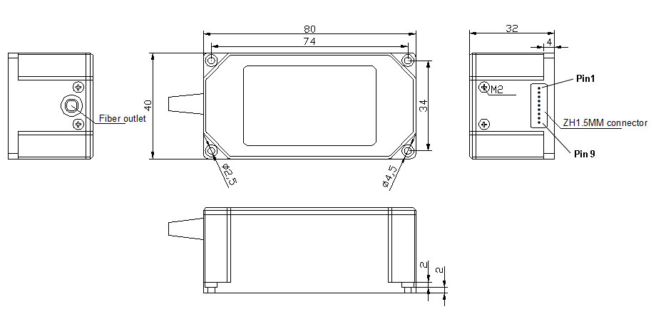

Fiber Optic Switches with ZH connector (1.5mm Pitch, 9 Pin)
Channel Amount (N) ≤ 16
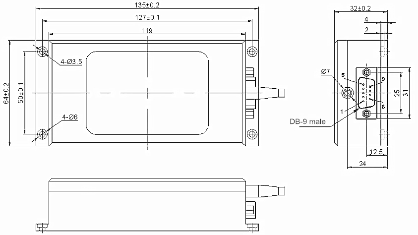
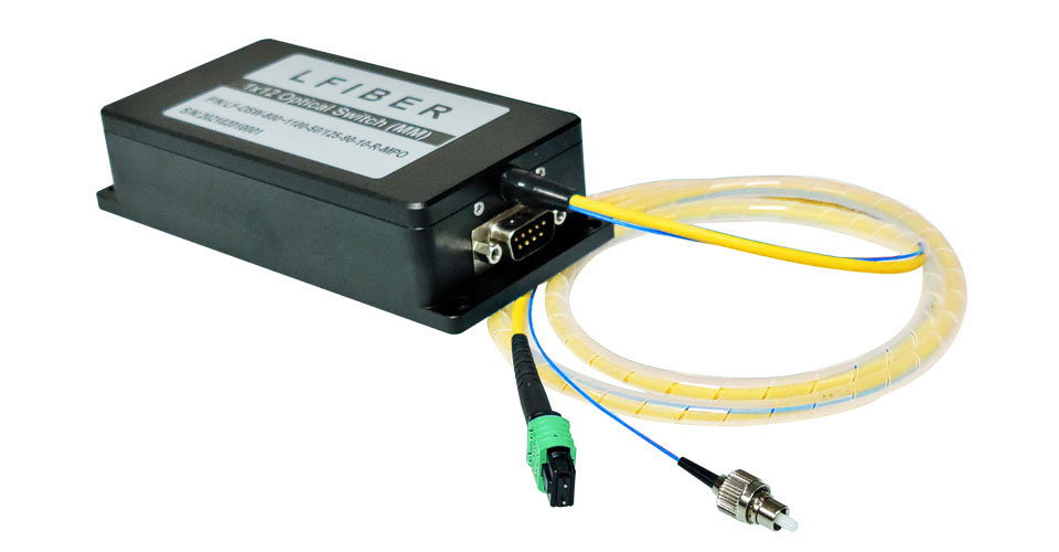
Fiber Optic Switches with DB-9 Male Connector
| Optical Route of the Fiber Optic Switches (Single-Mode Optical Switch) |
|---|
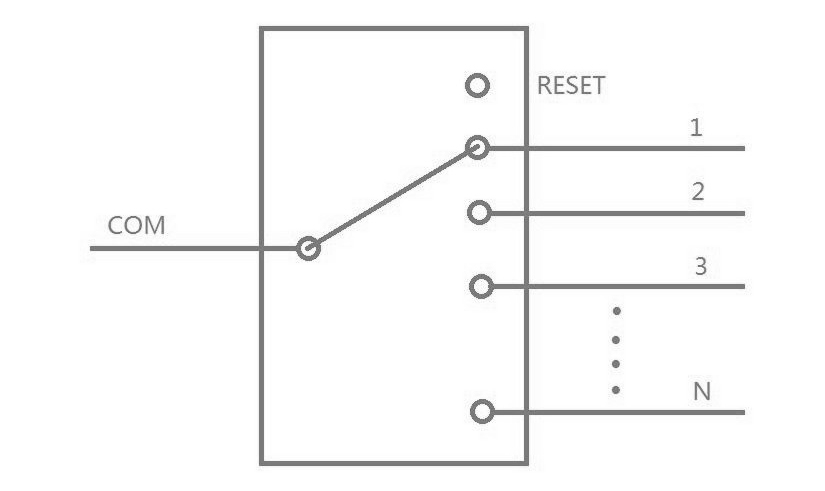
| Control Chart of the Fiber Optic Switches (Single-Mode Optical Switch) |
|---|
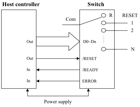
| Timing Diagram of Fiber Optic Switches (Single-Mode Optical Switch) |
|---|
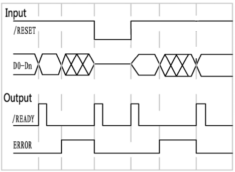
Operating Instructions
(1) Lfiber’s single-mode fiber optic switches have TTL/CMOS parallel interface. To distinguish from each other, there is a mark of a number for each of the connectors. The switches are bidirectional in operation.
(2) The fiber optic switches can be controlled via TTL/CMOS parallel interface with a DB-9 connector. See the Pin Specifications and Control Chart to set the connection correctly before operations.
(3) When supply power to the switch, it will reset the 0 channel. When /READY and ERROR signals become low, the switch is ready for the data or the reset signal.
(4) Channel Selection: Set /READY signal high and then connect the data lines to select the channel. Whenever the data exceed N (the max channel of the switch), the ERROR signal becomes high, until a correct data occurred or RESET signal is given. The fiber optic switch will monitor the data lines, and switch to the position specified by the data lines.
(5) Reset Operation: Set /RESET signal low, and the device will switch to the open position. /READY and ERROR signals become low after reset operation. Never try to keep /RESET signal low all the time otherwise the fiber optic switches will repeat the reset operation until the signal goes high. The low level on the /RESET pin should not exceed 20ms.
(6) The /READY signal keeps high when the fiber optic switches are in operation (switching) and it becomes low after operations. The ERROR signal keeps high when an invalid data appears on the data line and it becomes low after reset operation or input a valid data. To understand the device’s operation situation, the /READY and ERROR signal should be monitored although D0~D3 data lines are enough for the simplest application.
Ordering Information for the Fiber Optic Switches (Single-Mode Optical Switch)
Number of Channels Operating Wavelength Fiber Type Control Mode Fiber Pigtail Length Connector
1x2 444 nm Single-mode fibers TTL 0.50 m None
1x4 450 nm 1.00 m LC/UPC
1x8 460 nm 1.50 m LC/APC
1x16 532 nm Custom … SC/UPC
Custom … 630 / 632 / 633 nm SC/APC
635 / 637 nm FC/UPC
650 nm FC/APC
780 nm MPO Male
793 nm MPO Female
830 nm Custom …
835 nm
850 nm
905 nm
915 nm
935 nm
940 nm
980 nm
1064 nm
1080 nm
1300 nm
1310 nm
1450
…
2000 nm
Custom …
Related Products of SM Fiber Optic Switches (Single-Mode Fiber Optical Switch)
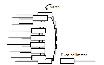 Inside the single-mode fiber optic switches, the mechanical movement of some parts controls the direction of the light signal or changes states between transmitting and cutting off the light signal.