What Is a Polarization Maintaining (PM) Fiber Optical Collimator
In fiber optical systems, the PM fiber collimators (450 nm, 460 nm, 630 nm, 632 nm, 650 nm, 780 nm, 850 nm, 980 nm, 1064 nm, 1310 nm, 1550 nm, 2000 nm) are used to either couple light from free space into an optical fiber or collimating light from a fiber to form a “collimated” optical beam. At the same time, The PM fiber collimator can fully preserve the polarization of light. Most in-line PM fiber optical modules consist of two face-to-face PM fiber collimators and of functional elements, such as filters, polarizers, or crystals, inserted in the free space between them.
Structure of a PM Fiber Collimator (Polarization Maintaining Fiber Optical Collimators)
 Fiber Optical Collimator 780nm 650nm 632nm 630nm 460nm 450nm 2000nm 1550nm 1310nm 1064nm 980nm 850nm")
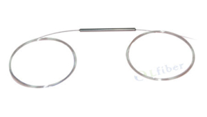
Figure 1 A structure of a Polarization Maintaining (PM) optical fiber collimator.

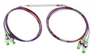
Light from a fiber is coupled into another fiber by means of a PM fiber collimator pair, pointing at each other.
Polarization Maintaining (PM) Fiber Optical Collimator
 Fiber Collimator")
FEATURES OF POLARIZATION MAINTAINING (PM) FIBER OPTICAL COLLIMATOR
- Low Insertion Loss
- High Extinction Ratio (ER)
- High Return Loss
- GR-1221-Core Compliant
APPLICATIONS OF PM FIBER COLLIMATOR
- Fiber-Optic Collimation and Focusing
- Essential Elements for PM Optical Devices
- Optical Communications Systems
- Other PM Fiber Optical Applications
Specifications of the PM Fiber Collimator
Center Wavelength(nm) 450, 460 630, 632, 650 780 850 980 1064 1310, 1550 2000
Operating Wavelength Range (nm) ±20 ±20 ±20 ±20 ±20 ±30 ±50 ±30
Insertion Loss (dB) ≤1.0 ≤0.8 ≤0.4 ≤0.35 ≤0.3 ≤0.3 ≤0.25 ≤0.5
Extinction Ratio (dB) ≥20, ≥25, ≥30, ≥35
Working Distance (mm) 5, 10, 20; Others upon request
Fiber Type Panda PM Fibers
Return Loss (dB) ≥55 (UPC), ≥60 (APC)
Operating Temperature (°C) -5 to +70; Others upon request
Storage Temperature (°C) -40 to +85
Package Dimensions (mm) Φ3.20*L10 (metal housing, Φ1.8mm lens)
Φ2.78*L9 (glass housing, Φ1.8mm lens)
Φ1.80*L7 (metal housing, Φ1.0mm lens)
Φ1.40*L7 (glass housing, Φ1.0mm lens)
Notes:
- For polarization maintaining (PM) fiber collimator with a connector, IL is 0.3 dB higher, RL is 5.0 dB lower, and ER will be 2.0 dB lower.
- Insertion loss is measured through a PM fiber collimator pair.
- Unless otherwise specified, the slow axis of the PM fiber is aligned with the key of the fiber connector.
- Please specify the operating wavelength, working distance, extinction ratio requirements, housing type (package dimensions), fiber length, connector type, etc. in the orders. (See the ordering information section.)
- This PM fiber collimator (high extinction ratio) is customizable, and the above specifications are subject to change without notice.
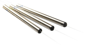
Package Dimensions of the PM Fiber Collimator


Ordering Information for PM Fiber Collimator
Wavelength Working Distance Extinction Ratio Package Dimensions Fiber Pigtail Fiber Length Connector
450 nm 5 mm ≥20 Φ3.20*L10 mm (metal) Φ250μm bare fiber
(without jacket)0.5 m None
460 nm 10 mm ≥25 Φ2.78*L9 mm (glass) Φ900μm loose tube 0.8 m FC/UPC
630 nm 20 mm ≥30 Φ1.80*L7 mm (metal) Φ2.0mm cable 1.0 m FC/APC
632 nm Others ≥35 Φ1.40*L7 mm (glass) 1.5 m SC/UPC
650 nm 2.0 m SC/APC
780 nm Others LC/UPC
850 nm LC/APC
980 nm Others
1064 nm
1310 nm
1550 nm
2000 nm


")


")


